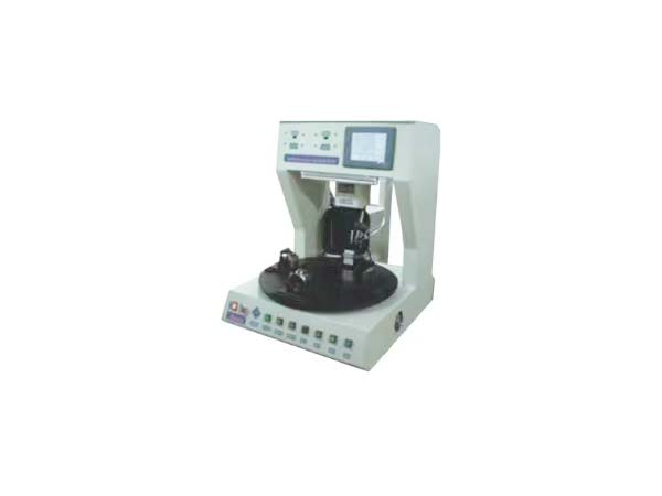
Non-standard automatic soldering machines achieve the automation of complex soldering tasks through the collaborative work of five core modules: customized hardware design, motion control, temperature management, process execution, and intelligent detection. The following is an analysis from the perspectives of technical logic and process:
I. Core Working Modules and Principles
Customized mechanical structure and motion control
Multi-axis linkage system
It is driven by X/Y/Z three-axis (or more axes) servo motors, combined with high-precision guide rails and lead screws, to achieve precise positioning of the solder head in three-dimensional space. For instance, when welding the mainboard of a mobile phone, the positioning accuracy of the X/Y axis can reach ±0.02mm, and the pressure control accuracy of the Z axis is ±0.1N, thus avoiding damage to components.
Flexible Fixture Design
Customize fixtures according to the product shape. For instance, design adjustable clamping modules for irregular-shaped connectors to be compatible with products of various sizes, and shorten the production change time to within 10 minutes.
2. Temperature management system
Instantaneous heating and precise temperature control
The soldering iron tip adopts a ceramic heating core, with a heating speed of no more than 3 seconds and a temperature fluctuation range of ±1℃ (closed-loop PID control). For instance, when soldering 0201 surface mount components, the set temperature is 350℃, but the actual fluctuation is only ±0.8℃, thus avoiding thermal damage to the components.
Nitrogen-protected welding
For high reliability requirements (such as automotive electronics), nitrogen is introduced around the solder head to reduce the formation of oxide layers and increase the tensile strength of the solder joints by more than 30%.

3. Supply and control of solder materials
Precision tin feeding mechanism
The gear pump is driven by a stepping motor, with a tin feeding accuracy of ±0.05mm. For instance, when soldering BGA chips, the amount of solder fed at one time can be precise to 0.1mg, avoiding solder balls or false soldering.
Tin breaking and slag removal function
The tin feeding tube is equipped with tin-breaking blades, which pre-cut the solder wire into a spiral shape to increase the fluidity of the solder and reduce spatter.
4. Process execution flow
Standardized welding procedures
Visual positioning: The position of the solder joint is identified through a CCD camera to compensate for product tolerances (such as ±0.1mm).
Preheating: Preheat large-sized pads (such as power devices) to prevent thermal shock.
Welding: The solder head comes into contact with the solder joint, pressure is applied and solder is fed. The welding time is precise to the millisecond level.
Cooling: Natural cooling or forced air cooling to ensure uniform crystallization at the solder joints.
Dynamic parameter adjustment
Automatically adjust the temperature, pressure and time according to the size of the solder joint. For instance, when welding a 0.5mm² pad, the temperature is 380℃, the pressure is 0.3N, and the time is 1.2 seconds. When welding 2mm² pads, the parameters are automatically adjusted to 400℃, 0.5N, and 1.8 seconds.
5. Intelligent detection and feedback
Solder joint quality inspection
Integrated AOI (Automatic Optical Inspection) system, it can detect the appearance defects of solder joints (such as bridging, solder balls, voids) in real time, with a detection speed of ≥500 solder joints per minute and a misjudgment rate of ≤0.5%.
Electrical performance testing
Through the four-wire resistance test module, the resistance of the solder joints is measured online (with an accuracy of ±0.1mΩ) to ensure conductivity.
Data Traceability and Alarm
Record the process parameters and inspection results of each solder joint. When there is an abnormality, automatically stop the machine and sound an alarm, and generate a quality report.
Ii. Examples of Working Principles in Typical Application Scenarios
Scene 1: Welding of automotive electronic controllers
Requirement: Solder the copper bars of the IGBT module. The solder joints need to withstand a current of 50A and a temperature range of -40℃ to 125℃.
Working principle
Laser-assisted heating is adopted to locally raise the temperature to 450℃, avoiding the expansion of the heat-affected zone.
The tin feeding mechanism provides high-silver content solder wire (SnAgCu), with a silver content of ≥3% at the solder joints, enhancing electrical conductivity.
After welding, the temperature of the weld point is monitored in real time by an infrared thermometer, and the cooling rate is controlled within 5℃/s to prevent thermal stress cracking.
Scene 2: Flexible circuit soldering for medical equipment
Requirement: Solder 0.1mm spacing gold fingers between FPC and PCB, and the solder joints need to pass a 1000-fold bending test.
Working principle
Use a micro soldering iron tip (with a diameter of 0.3mm) and apply low pressure (0.2N) for soldering to prevent damage to the FPC substrate.
Low-temperature solder paste (melting point 138℃) is adopted to reduce thermal stress.
After welding, the reliability of the weld points is automatically detected by the bending test module, and non-conforming products are automatically diverted.
about
Introduction video case honor partners factoryproduct
Automatic welding line Non-standard customization Automatic soldering Glue/screw lockingnews
dynamic Information faqCustomer Service
contactMr. Xia:+86 186-7696-3763

WeChat QR code

Douyin QR Code
Copyright © 2025 Copyright © Dongguan Chuangxiao Automation Technology Co., Ltd.
本站相关网页素材及相关资源均来源互联网,如有侵权请速告知,我们将会在24小时内删除